piezo

Electrolier (September night in Virginia) by kelly heaton

​I've been working around the clock to finish my Hackaday Prize application and pack for Hacking Nature's Musicians in Mexico. As closure for my recent chapter, the various circuits that I've shown you over the past few weeks have migrated from my bench and into a sculpture titled "Electrolier (September night in Virginia)," 2018. Here​ is an informal video:

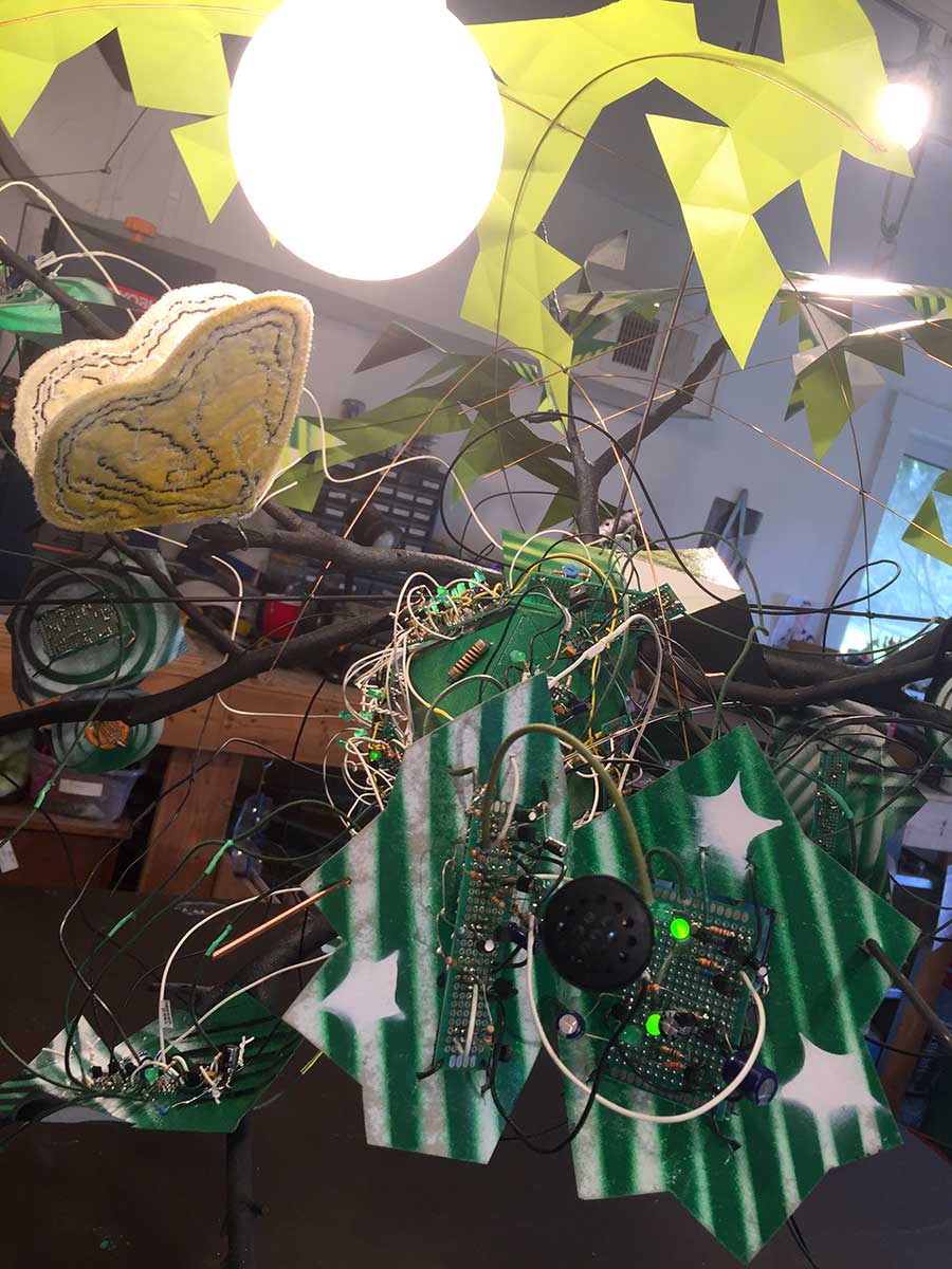
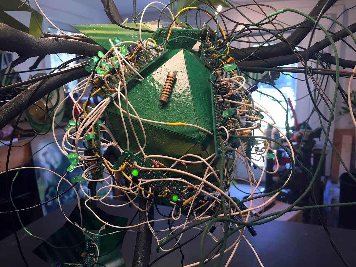
The video quality isn't great... (shot with my iPhone under bad lighting and extremely messy studio)... but hopefully you get the idea. The sculpture contains one instance of my Mother Nature board design, recognizable by the dense tangle of white wires connecting logic gates, and six sound generating "animal circuits" each with its own speaker. The colorful graphics are spray painted cardboard, and everything is hung on a tree structure under a moon (globe pendant bulb). Oh, and that large moth is made out of silk velvet that I dyed and embroidered with an old industrial "Ultramatic" machine​. I would have used small molex-style connectors to connect everything, but there was no time.

It's interesting that so many long wires didn't screw up my signals. I credit this to my use of common emitter amplifiers to buffer the signals, and the fact that I'm not drawing much current for anything you see (or hear). The whole sculpture is powered with a 12VDC / 1.5 amp power supply. I also used multiple 0.1 uF ceramic capacitors between power and ground on most of the individual perfboards. It's critical to remember power-ground capacitors when you're dealing with a lot of amplified signals banging on your power rails. I'm careful to avoid really small gauge wire, and I add many pathways to ground ("let ground abound.")

So... now I am packing my electronics bench into a suitcase and praying that security does not detain me at the airport. I'm throwing in packets of desiccant and crossing my fingers that jungle humidity doesn't zap everything. Making analog electronic circuits in the jungle will be interesting to say the least -- stay tuned for the sounds of los músicos de la naturaleza​ en Quintana Roo!

Prototyping Night Insects by kelly heaton

Here I am at my bench prototyping various analog electronic insects for my latest "electrolier" sculpture. The sounds are made using a combination of astable multivibrators (oscillators), some of which create the audio timber and others establish a chirp-like tempo. The speakers are custom piezo electric devices that I have physically modified to achieve different sound qualities, such as brighter versus muffled and close versus distant. Individuality is achieved by subtle variations in the electrical signal and the output device.

Piezo speaker housing by kelly heaton

Here's a prototype of a housing for a piezo speaker that I will actuate with analog electronic insect sounds. The shape of the housing and mechanical pressure on the piezo element will change the pitch as well as the volume. I made this housing by first laser cutting 1/4" acrylic and gluing the stacked rings to make a pyramidal-shaped buck — see images below. Note that there's a central hole all the way through the buck to aid the vacuum forming process. I’ve vacuum-formed .080” and .090" acrylic sheet over the buck (both work fine) and used a laser to cut the shapes out. My registration needs improvement, but you get the idea. The piezo element is mounted inside of the housing by a short length of plastic tube that I glued in place.

Below I show my process to cast the acrylic buck in plaster (using an alginate mold). I will use plaster, wood, or metal bucks in the future because acrylic deforms in the vacuum forming process. In either case, it is critical to use mold release.

Why am I doing this? Because when RadioShack went out of business, I could no longer buy the piezo speakers that I used for my insect sounds. I was forced to reverse engineer the part --which turned out to be a blessing because the sound of insects is heavily dependent upon the mechanics of speaker design (not just the electronics which drive the speaker). For a previous blog entry on this issue, link here or read about my project “Hacking Nature’s Musicians” on Hackaday.io

Cricket Circuit by kelly heaton

The chirping piezo electric circuit from my last post is getting a body. I did the layout in KiCad and sent my boards for manufacture by PCBWay (based on a colleague's recommendation). Their interface is not as user-friendly as OSH Park, but they offer a variety of solder mask colors - not just purple. I ordered this guy in black. I'll post an update when the boards are wired up and chirping.

Board layout in KiCad

Board layout in KiCad

KiCad 3d simulation of the pcb

KiCad 3d simulation of the pcb

Piezo acoustics by kelly heaton

This will be one in a series of blog entries about engineering, as I am building a new "electrolier" sculpture from scratch.

Sometimes, art requires that I push myself into the non-linear intelligence of my right brain, what Carlos Castenada refers to as the nagual - a consciousness distinct from reason that is non-verbal and non-analytical. Other times, art requires that I focus on the tonal, or my capacity for reason and logic. Engineering is an extremely tonal activity. This is my current mind-frame out of necessity.

The insect noises that I create for my art rely on a piezo electric disk element. (I will save "why" for another blog entry on the nature of sound.) I have used piezo buzzers manufactured by Radioshack for at least a decade, notably parts #273-059 and #273-060, as I find their sound character and ease-of-use to be optimal. However, these buzzers became hard to get when RadioShack went out of business a few years ago, and I was forced to find a substitute. What was initially a pain has turned out to be good fortune, as I have learned how the buzzers work, designed a less expensive solution, and discovered new opportunities to shape sound.

Fumble number one was my discovery that not all piezo disks are made equal. Some have two contacts and are best suited for electrical pick-up (like listening to tiny sounds). The kind used in a RadioShack buzzer is a piezo with feedback and has three contacts: M (main), F (feedback), and G (ground). "M" is sometimes associated with a red wire, "F" a blue wire, and "G" a black wire -- just in case you encounter this color-coding, but don't get confused when you look at my piezo disk below because I substituted a white wire for the "F" contact.

Piezo disk elements also have different resonances, so you need to get the right one for your sound. RadioShack buzzers are in the 2.8 - 3.6 Hz range. I bought comparable piezo elements from Digikey, like the one pictured above right: https://www.cui.com/product/resource/ceb-35fd29.pdf

The next challenge I confronted is how to drive the raw piezo element. RadioShack buzzers include an internal amplifier circuit (see below left), so I reverse engineered their design. It's a simple NPN transistor amplifier - I found that BC547 works well. Below you can see the RadioShack circuit on the left and my KiCad schematic on the right. My unspecified resistor and capacitor to ground are optional, although I almost always use a resistor to ground (like 1K). If you don't use a resistor or capacitor to ground, then you must place a jumper wire here.

On to the next step, was to lay-out my design for the printed circuit board. 

The image on the left shows the board with the ground fills turned off (so you can see the traces). The two images on the right are a KiCad simulation of the actual board, which I'm having made by PCBWay in China (as of April 2, 2018).