
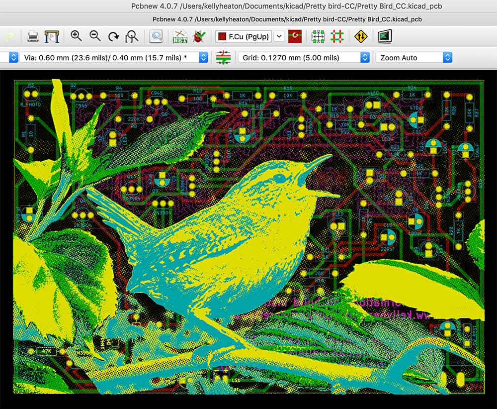
2019 circuit board designed in KiCad (colors correspond to KiCad layers - not my choosing, but interesting op art effect). The circuit sings a simple “pretty bird” song as demonstrated in the following video…
board
birds and electricity /

Detail of new work in progress concerning birds and electricity, 2019
Moth Circuit /
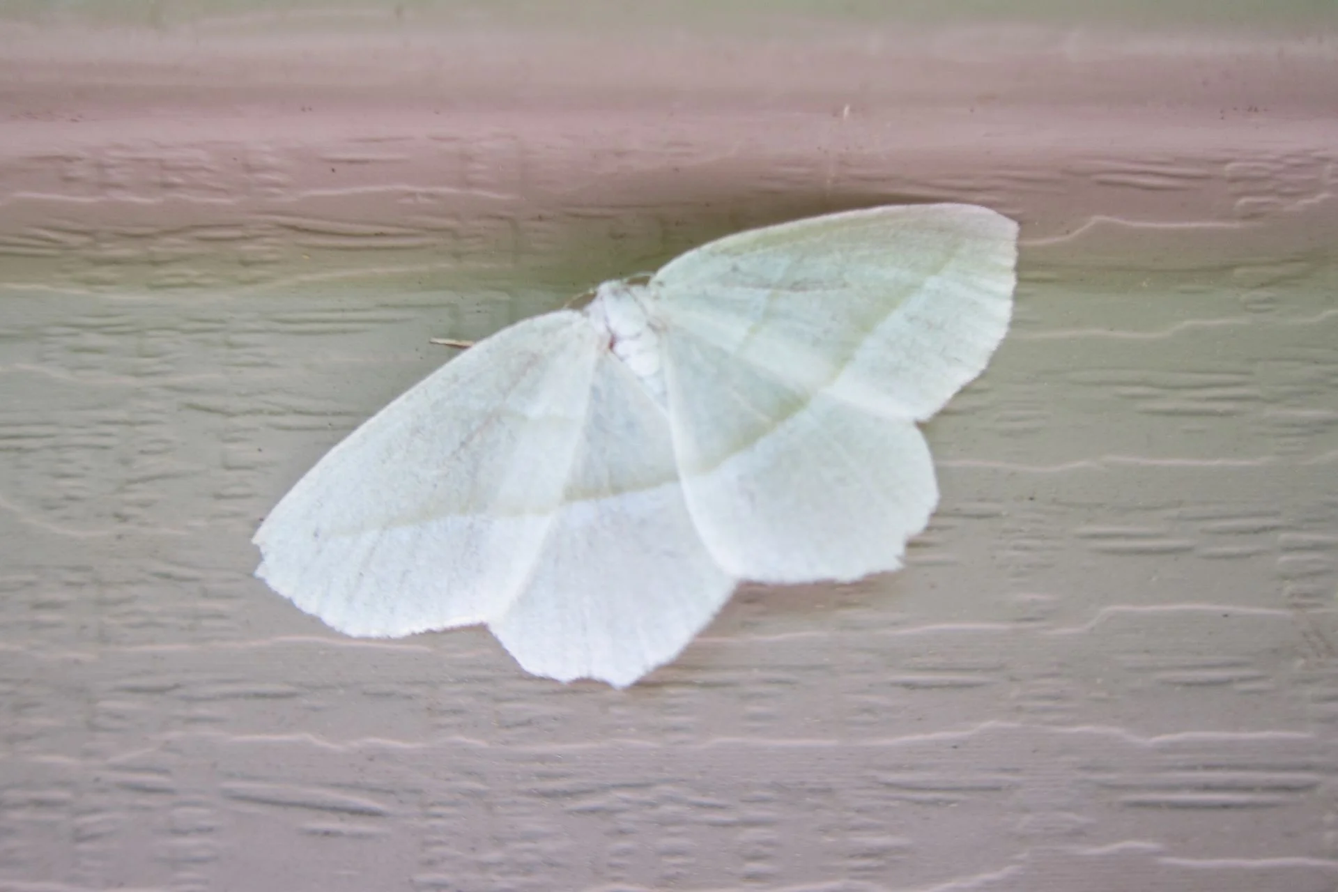
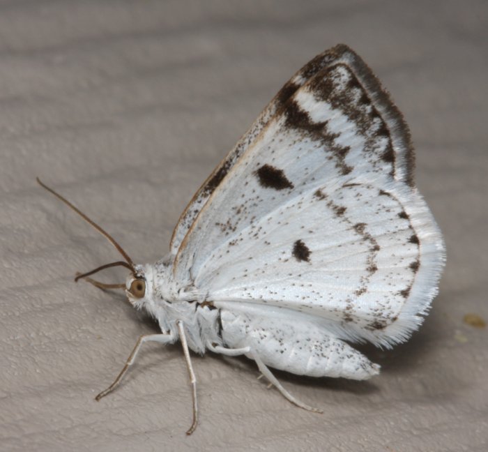
I continue to design circuits for the night-dwelling inhabitants of my latest electrolier. Here's a little white moth. It's two wings are separate boards comprising a single functional circuit that I'll join in the middle with wires. Its circuit is an adaptation of the well-known "Knight Rider" design: a 555 timer in astable mode that clocks a 4017 counter. I have selected resistor and capacitor values to blink the LEDs with a flutter effect, and there are several optional inputs to the moth whereby external circuits can add "noise," i.e., random behaviors that give a natural appearance. I will update you when the boards arrive and are wired up... fingers crossed that my design contains no errors, as drawing with copper traces is not the most straightforward way to visualize electrical connectivity. Below are two moth images pulled from the Internet for inspiration, followed by my circuit board design in KiCad software.

Two views of my moth in KiCad. The top image shows a 3d rendering of the actual boards, and the bottom shows my printed circuit board (PCB) layout. Kelly Heaton, 2018
Cricket Circuit /
The chirping piezo electric circuit from my last post is getting a body. I did the layout in KiCad and sent my boards for manufacture by PCBWay (based on a colleague's recommendation). Their interface is not as user-friendly as OSH Park, but they offer a variety of solder mask colors - not just purple. I ordered this guy in black. I'll post an update when the boards are wired up and chirping.

Board layout in KiCad

KiCad 3d simulation of the pcb