
Pretty bird, 2019 - 2022


“Hail to thee, blithe Spirit! Bird thou never wert,..”
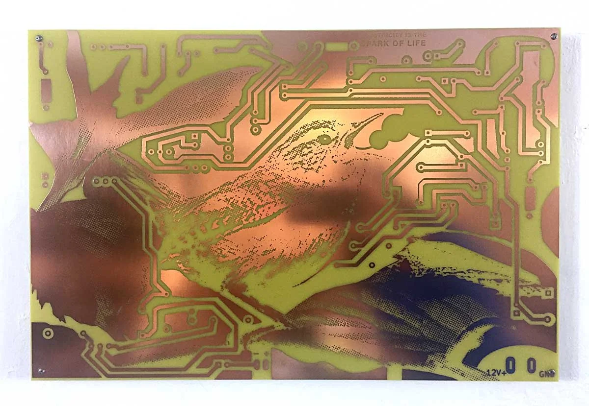
Pretty Bird combines my practice of Electronic Naturalism with circuit board printmaking. The art generates a bird-like chirping sound that is reminiscent of a Carolina wren. The effect is pure electronic vibration: no digital code or audio recording. Electricity flows through the scene causing the circuit to vibrate, and we hear these vibrations as birdsong.
The Visual Composition
A Carolina wren is etched in exposed copper and electroplated with gold. She sits on a leafy branch in a forest made with green epoxy soldermask. Where the copper has been etched away, areas of exposed fiberglass define the functional circuit traces and give depth to the image. A white screen-printed layer adds visual highlights to the bird and leaves. Sculptural “through hole” electronics enhance the forest with dimensionality and texture. Backlighting gives the piece a watermark effect thanks to the translucency of fiberglass (versus the opacity of copper and solder mask).


a brief history of printed circuit boards in art
Paul Eisler invented printed circuit boards in the mid-twentieth century, and the hacker badge movement dates back to 2005 (Read Joe Grand’s presentation here). The manufacturing techniques used for Pretty Bird are common in industrial circuitboard manufacturing. However, Pretty Bird ver.CC (2019) is one of the earliest examples of circuit board printmaking used in fine art. This is because, until recently, manufacturing was too difficult and few artists had the necessary engineering skills. PCB manufacturing has become much more accessible, although the tools and training for aesthetic circuit design are still obscure. However, this is changing with a new generation of technologically fluent artists such as Brian Oakes and Emmett James Palaima.
Pretty Bird Versions
The first edition of Pretty Bird (ver.CC, 2019) was an edition of 150 kits with a printed circuit board and associated parts. The edition was commissioned by Creative Capital for their 20th anniversary retreat celebration. This work of art —a multiple— is complete regardless of whether the owner elects to assemble it. Whether or not the circuit “lives” is irrelevant because living and dying are part of the electronic naturalism cycle. Big Pretty Bird, 2019 is an edition of 3 artworks assembled, signed and numbered by the artist. Pretty Bird for Circuit Icon, 2022 is an unnumbered electronic art edition. The Making of a Pretty Bird, 2019 is a non-functioning, unnumbered series with three panels that show how the circuit was made. The series was commissioned by the Indigo Hotel Group for Hotel Chattanooga, TN.


Pretty Bird electronics and circuit assembly
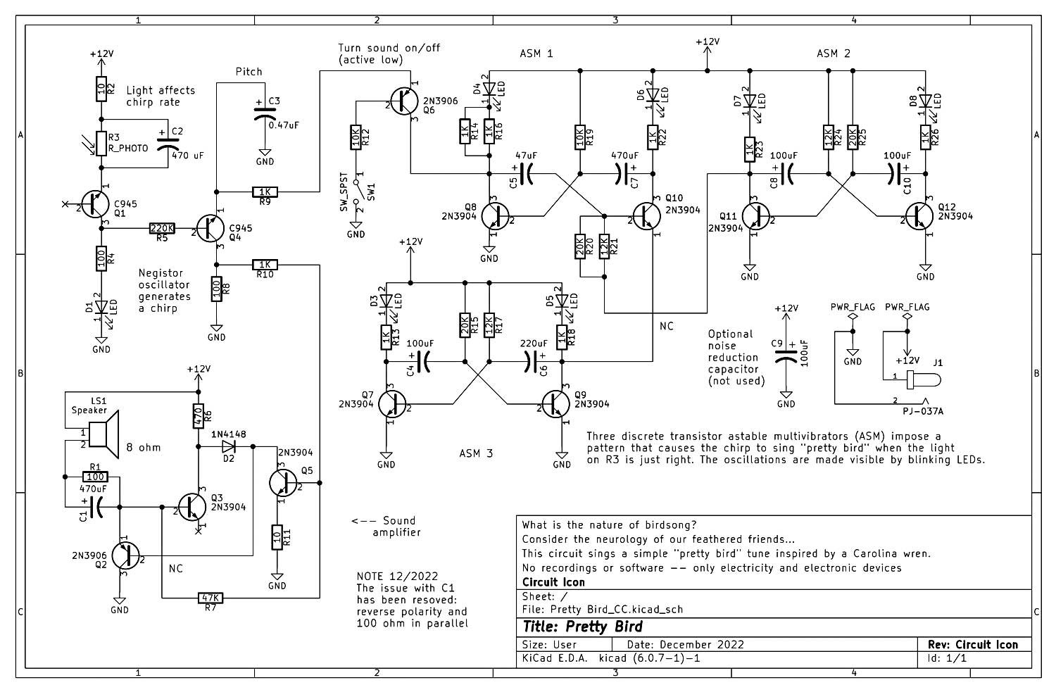
The Pretty Bird schematic, 2023 (still applicable to the 2019 design but reflecting some minor corrections)
Electronic parts required to assemble the Pretty Bird CC 2019 circuit.
Quantity 1: 0.47 uF electrolytic capacitor (C6)
Quantity 4: 100 uF electrolytic capacitor (C8, C12, C13) *C3 is unused - leave empty
Quantity 1: 220 uF electrolytic capacitor (C10)
Quantity 1: 47 uF electrolytic capacitor (C9)
Quantity 3: 470 uF electrolytic capacitor (C1, C2, C11)
Quantity 1: 1N4148 general purpose signal diode (D4)
Quantity 7: Green light emitting diode aka “LED” (D1, D2, D3, D6, D7, D8, D9)
Quantity 1: 2x5.5MM power jack (J1)
Quantity 1: 8 ohm speaker (LS1)
Quantity 8: 2N3904 NPN transistor (Q4, Q7, Q9, Q11, Q12, Q13, Q14, Q15)
Quantity 2: 2N3906 PNP transistor (Q3, Q10)
Quantity 2: KSC945Y NPN transistor (Q2, Q6)
Quantity 2: 10 ohm resistor (R1, R12)
Quantity 2: 100 ohm resistor (R4, R10)
Quantity 3: 12K ohm resistor (R20, R23, R26)
Quantity 2: 10K ohm resistor (R16, R22)
Quantity 8: 1K ohm resistor ((R13, R14, R17, R19, R21, R24, R25, R28)
Quantity 2: 20K ohm resistor (R18, R27)
Quantity 1: 220K ohm resistor (R8)
Quantity 1: 470 ohm resistor (R7)
Quantity 1: 47K ohm resistor (R2)
Quantity 1: Light-dependent resistor (R3)
Quantity 1: On/off slide switch (SW1)
Quantity 1: 12 volt DC power supply with minimum 300 mA. You must supply your own.
NOTES:
— Reverse the polarity of the electrolytic capacitor at C1 and solder a 100 ohm resistor across it.
— Solder an additional 1K resistor in parallel with the resistor at position R19.
— Solder an additional 20K resistor in parallel with the resistor at position R23.
Thank you David Swanson for fixing the capacitor issue at C1 and @DJ Mystic from Hackaday.io for the negistor oscillator design.