hacker

Mother Nature in perfboard by kelly heaton

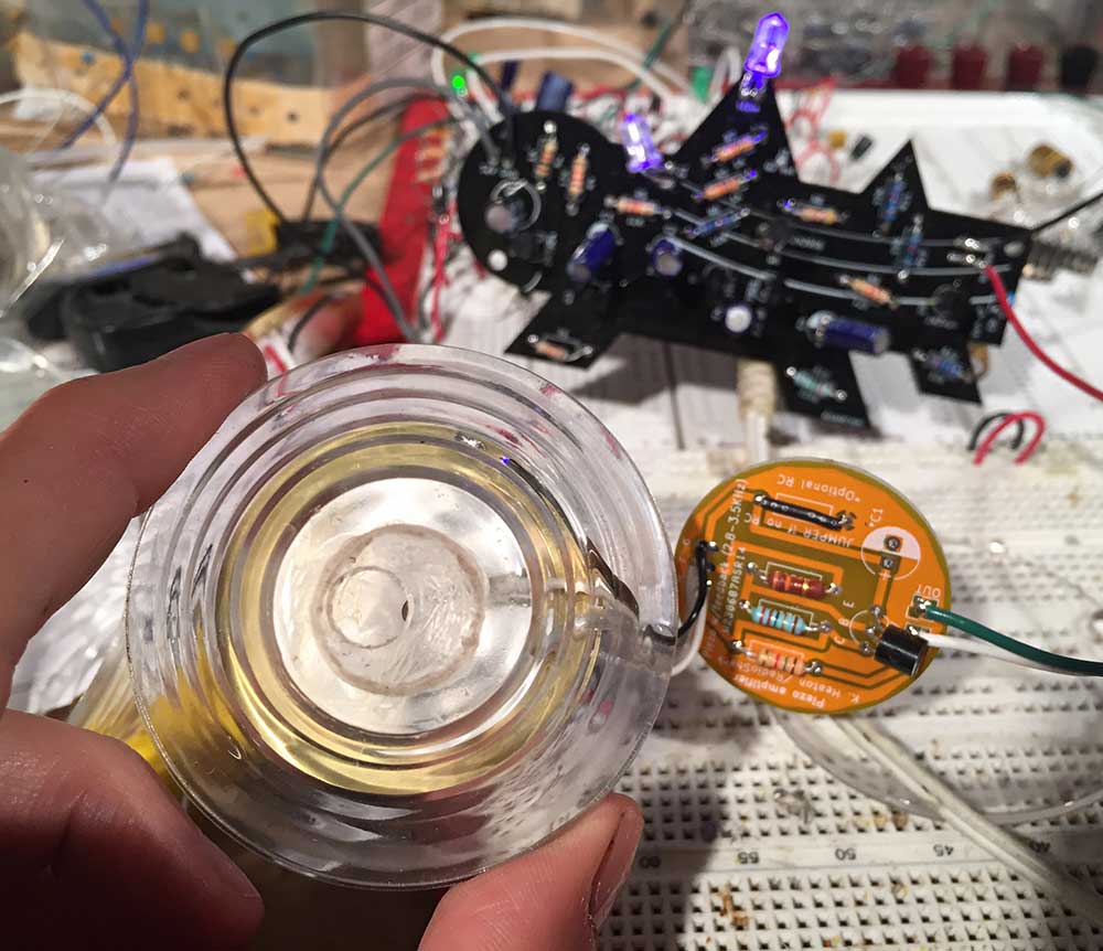
I've been busy migrating my "Mother Nature" controller circuit out of my breadboard and into perfboard... and yes, it's insane but no, I don't have time to produce a printed circuit board because I'm leaving in six days for a fellowship in Mexico. For the record, I do not recommend soldering so many components and connections in perfboard because the risk of error is high, either from bad solder joints, signal interference, or just plain confusion. I plan to design a printed circuit board for future embodiments of Mother Nature. Stay tuned.

As you can see in my previous log, I'm surrounding my perfboard circuits with spray painted cardboard to make them look cool -- and by the way, you could use this quick-and-dirty strategy to make a "starving artist's badge" for the Hackday Superconference.

Kelly Heaton process electronic

As for the design of my "Mother Nature Board," aka random pulse generator to trigger various events, I have some additional technical tips to share:

  • Don't have logic ICs on hand? Build discrete transistor gates. This approach has the advantage of common components (NPN transistors, resistors, diodes) and you can add multiple inputs to the same gate -- which is useful if you discover that an event is triggering too often... just add another input to the gate and the outcome will become less frequent. Not triggering often enough? Remove or change an input to the gate. You can even tie an input to ground (or power) and let the other fluctuate. I use 2N3904 transistors for as many things as possible, but you could also build these cool light gates described by @Dr. Cockroach 

discrete_logic_gates.jpg

There's a limit to how many things you can drive directly with a signal such as the output of a logic gate. Good engineers read data sheets and calculate voltages and current at various locations in their circuit. Impatient engineers add a generic common emitter amplifier between the signal OUT from a logic device and the signal IN to whatever you're driving. This hand-waving approach to buffering will not work in all cases! But it will probably work for most slow logic applications where you want to transform a signal multiple times and drive some light loads. I'm an artist who prefers prototyping to math, so I work a lot with "try it and see" circuit design. Plus, I am not building a nuclear reactor. Note that a common emitter amplifier will invert your signal. Pay attention to whether you need your signal to be active high or active low. Note that a 555 timer in monostable aka one-shot configuration is looking for an active low input. If necessary, invert the signal again to get what you need.

common-emitter-amplifier.jpg

Mosfets make great electrical "on/off" switches because they don't draw current on their gate (==the mosfet equivalent of a transistor's base). They just need a voltage. I use mosfets for the last step in my Mother Nature circuit, or the point at which I want to turn power on or off to a particular sound circuit (the load). Make sure you have a gate resistor to ground or voltage will "sit" on the gate even when the signal is low (and the mosfet won't turn off).

mosfet-switch.jpg

I hope these tips are helpful. To end this log, I give you a video showing my Mother Nature circuit in perfboard with two sound circuits hooked up. If you watch the LEDs carefully, you will see how certain combinations of logic are triggering the sound circuits. The cricket is wired up to chirp most of the time, whereas the Katydid is triggered less frequently. For this demo, I hooked up only two sound circuits because it's already hard to understand what is happening, and more circuits becomes a sort of natural chaos... which is my goal, as you will see in forthcoming logs.

Owl surgery by kelly heaton

Paper owl looking onto its electronic eye circuit, 2018

Paper owl looking onto its electronic eye circuit, 2018

Transitions. Sometimes it feels like the holes that we have are equally -if not more- beautiful than what promises to fill them. Here, a paper owl contemplates the circuit that I designed to fit into its eyes. The addition of electronics to a static object adds more than functionality and aesthetics - it changes the identity of the object. Non-electronic things live in a physical world with thousands of years of creative history, while electronic things are very new. What was once an owl then become a robot - perhaps more robot than owl in our estimation. Does the owl stand to lose more than it gains?

Shift registers by kelly heaton

I am in the process of building a control system for the insects in my latest Electrolier. As a starting point, I will use shift registers with (or possibly without) linear feedback. Adding linear feedback involves "tapping" two or more of the logical outputs, evaluating their state with boolean logic (usually an XOR gate), and feeding the result back into the start of the shifting sequence. In my video, you can see two 8-bit shift registers in the center (TI part number CD54/74AC164E). I put LEDs on the logic outputs Q0-Q7 to visualize what is happening. As you can see, the LEDs of the two shift registers are not synchronized, a property of an undefined starting state that I will exploit to get randomness for "free" -- at least that's what I'm thinking.

More about my breadboard: on the right is a 555 timer in astable mode which provides a clock pulse of about 1x per second. On the left is a 5 volt regulator - this part is irrelevant if you have the correct DC supply voltage, but mine is 12 VDC.

Good general overview to answer the question “what is a linear feedback shift register” (LFSR):
https://zipcpu.com/dsp/2017/11/11/lfsr-example.html

On choosing taps for a linear feedback shift register:
https://cs.stackexchange.com/questions/1121/choosing-taps-for-linear-feedback-shift-register

Mini project on how to implement a LFSR: https://www.slideshare.net/KishoreChandrahasVanam/lfsr

Another helpful paper on using an 8-bit LFSR (i.e. Texas Instruments chip CD54/74AC164):
https://pdfs.semanticscholar.org/320a/8b2e781ac6165b400eca96047489685fd1f7.pdf

One final note: because shift registers are comprised of flip flops, an option to add true randomness to this otherwise pseudorandom bit generator is to exploit the metastability characteristics of a flip-flop as described here by @crj11: https://electronics.stackexchange.com/questions/394557/old-school-pseudorandom-pulse-generator-requesting-assistance-with-hardware-des?noredirect=1#comment965703_394557

Piezo speaker housing by kelly heaton

Here's a prototype of a housing for a piezo speaker that I will actuate with analog electronic insect sounds. The shape of the housing and mechanical pressure on the piezo element will change the pitch as well as the volume. I made this housing by first laser cutting 1/4" acrylic and gluing the stacked rings to make a pyramidal-shaped buck — see images below. Note that there's a central hole all the way through the buck to aid the vacuum forming process. I’ve vacuum-formed .080” and .090" acrylic sheet over the buck (both work fine) and used a laser to cut the shapes out. My registration needs improvement, but you get the idea. The piezo element is mounted inside of the housing by a short length of plastic tube that I glued in place.

Below I show my process to cast the acrylic buck in plaster (using an alginate mold). I will use plaster, wood, or metal bucks in the future because acrylic deforms in the vacuum forming process. In either case, it is critical to use mold release.

Why am I doing this? Because when RadioShack went out of business, I could no longer buy the piezo speakers that I used for my insect sounds. I was forced to reverse engineer the part --which turned out to be a blessing because the sound of insects is heavily dependent upon the mechanics of speaker design (not just the electronics which drive the speaker). For a previous blog entry on this issue, link here or read about my project “Hacking Nature’s Musicians” on Hackaday.io