Embroidering moth wings by kelly heaton

I've been working at Nova Labs in Reston, VA to embroider wings for some of the moths in my new Electrolier sculpture. Here's some informal documentation of my process. The machine is an old industrial "Ultramatic" that was restored by a Nova Labs steward.

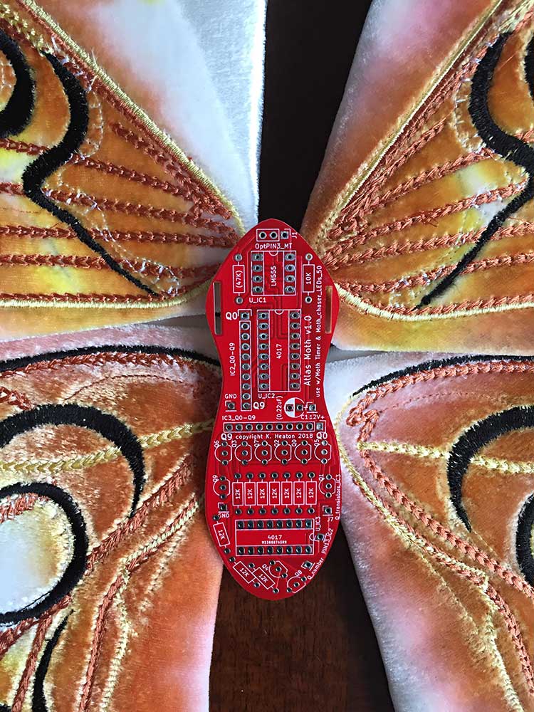
I dyed the velvet to give a "loose" colored background that contrasts with the precise stitches. (My registration was off on some of the wings, as you can see if you look closely at the color placement.) I embroidered both sides of the wings, which you can see above prior to assembly of the front and back parts. The middle image shows my "Atlas Moth" circuit board that forms the body -- more on that to come.

Tree cricket prototype by kelly heaton

I'm working on a prototype for a series of tree crickets (for my latest "electrolier" sculpture). This board is a little analog synthesizer with options to adjust resistor and capacitor values, thereby achieving different insect sounds. The video shows only one of the sounds --I'll demonstrate others later. 

The wings were laser cut out of Dura-Lar at the Nova Labs Makerspace in Reston, VA. In the video, I'm holding a wire spool to amplify the raw piezo element, for which I need to make a resonant chamber. The piezo is driven with my little "RadioShack copy" amplifier circuit that I blogged about recently (March 12). The board was manufactured in China by PCBWay.

Cricket PCB by kelly heaton

My first cricket circuit board arrived today and it chirps!

Astable multivibrator circuit built with discrete transistors. The circuit generates a waveform that sounds like a cricket when applied to a piezo electric buzzer. Kelly Heaton, 2018

Astable multivibrator circuit built with discrete transistors. The circuit generates a waveform that sounds like a cricket when applied to a piezo electric buzzer. Kelly Heaton, 2018

I did make one error in my schematic, which involved the reversal of the PNP transistor (3906). Thankfully, the wiring worked perfectly when I turned the PNP in the opposite direction.

Moth Circuit by kelly heaton

I continue to design circuits for the night-dwelling inhabitants of my latest electrolier. Here's a little white moth. It's two wings are separate boards comprising a single functional circuit that I'll join in the middle with wires. Its circuit is an adaptation of the well-known "Knight Rider" design: a 555 timer in astable mode that clocks a 4017 counter. I have selected resistor and capacitor values to blink the LEDs with a flutter effect, and there are several optional inputs to the moth whereby external circuits can add "noise," i.e., random behaviors that give a natural appearance. I will update you when the boards arrive and are wired up... fingers crossed that my design contains no errors, as drawing with copper traces is not the most straightforward way to visualize electrical connectivity. Below are two moth images pulled from the Internet for inspiration, followed by my circuit board design in KiCad software.

Two views of my moth in KiCad. The top image shows a 3d rendering of the actual boards, and the bottom shows my printed circuit board (PCB) layout. Kelly Heaton, 2018

Two views of my moth in KiCad. The top image shows a 3d rendering of the actual boards, and the bottom shows my printed circuit board (PCB) layout. Kelly Heaton, 2018

Cricket Circuit by kelly heaton

The chirping piezo electric circuit from my last post is getting a body. I did the layout in KiCad and sent my boards for manufacture by PCBWay (based on a colleague's recommendation). Their interface is not as user-friendly as OSH Park, but they offer a variety of solder mask colors - not just purple. I ordered this guy in black. I'll post an update when the boards are wired up and chirping.

Board layout in KiCad

Board layout in KiCad

KiCad 3d simulation of the pcb

KiCad 3d simulation of the pcb

Piezo acoustics by kelly heaton

This will be one in a series of blog entries about engineering, as I am building a new "electrolier" sculpture from scratch.

Sometimes, art requires that I push myself into the non-linear intelligence of my right brain, what Carlos Castenada refers to as the nagual - a consciousness distinct from reason that is non-verbal and non-analytical. Other times, art requires that I focus on the tonal, or my capacity for reason and logic. Engineering is an extremely tonal activity. This is my current mind-frame out of necessity.

The insect noises that I create for my art rely on a piezo electric disk element. (I will save "why" for another blog entry on the nature of sound.) I have used piezo buzzers manufactured by Radioshack for at least a decade, notably parts #273-059 and #273-060, as I find their sound character and ease-of-use to be optimal. However, these buzzers became hard to get when RadioShack went out of business a few years ago, and I was forced to find a substitute. What was initially a pain has turned out to be good fortune, as I have learned how the buzzers work, designed a less expensive solution, and discovered new opportunities to shape sound.

Fumble number one was my discovery that not all piezo disks are made equal. Some have two contacts and are best suited for electrical pick-up (like listening to tiny sounds). The kind used in a RadioShack buzzer is a piezo with feedback and has three contacts: M (main), F (feedback), and G (ground). "M" is sometimes associated with a red wire, "F" a blue wire, and "G" a black wire -- just in case you encounter this color-coding, but don't get confused when you look at my piezo disk below because I substituted a white wire for the "F" contact.

Piezo disk elements also have different resonances, so you need to get the right one for your sound. RadioShack buzzers are in the 2.8 - 3.6 Hz range. I bought comparable piezo elements from Digikey, like the one pictured above right: https://www.cui.com/product/resource/ceb-35fd29.pdf

The next challenge I confronted is how to drive the raw piezo element. RadioShack buzzers include an internal amplifier circuit (see below left), so I reverse engineered their design. It's a simple NPN transistor amplifier - I found that BC547 works well. Below you can see the RadioShack circuit on the left and my KiCad schematic on the right. My unspecified resistor and capacitor to ground are optional, although I almost always use a resistor to ground (like 1K). If you don't use a resistor or capacitor to ground, then you must place a jumper wire here.

On to the next step, was to lay-out my design for the printed circuit board. 

The image on the left shows the board with the ground fills turned off (so you can see the traces). The two images on the right are a KiCad simulation of the actual board, which I'm having made by PCBWay in China (as of April 2, 2018). 

Electricity Maker by kelly heaton

Electricity Maker, 2018. Watercolor and pencil on paper, 15" x 11"

Electricity Maker, 2018. Watercolor and pencil on paper, 15" x 11"

Yesterday, I had a great visit to the Phillips Collection in Washington D.C. They have a wonderful collection of 20th century paintings in which the artists try to express energies that are *almost* visible. Of course, I saw electricity everywhere! Especially Charles Burchfield and Vincent Van Gogh were operating on the boundary of what can be seen with the physical eyes and what can be sensed with the "third eye" of perception. I also enjoyed their "After Paul Klee" exhibit, especially artists working with ancient symbols and petroglyphs to find new languages to describe psychological, cultural, and perceptual realties that do not convey with representational painting.

Here, I have pushed the language of electronics (elements of a circuit) to adopt the tribal, ritual form of an "electricity maker." The surrounding landscape is vibrating with natural and unnatural energy.